Authors: Peter Anderson, Wade Goodridge, Sarah Lopez, Natalie Shaheen
Class Size
- Written for 15 students
Lesson Structure
150 minutes
- Pavilion introduction - 15 minutes
- Sheathing test - 25 minutes
- Calculating tributary area - 25 minutes
- Assemble the box - 30 minutes
- Assemble gables - 85 minutes
Objectives
Students will be able to:
- Construct a gabled roof with rafters of their own design.
- Calculate tributary area of a gabled roof.
- Decide on sheathing width and rafter spacing based on provided data.
Prerequisite Knowledge
- Students have a value for the Total Roof Load on their structure from Columns of Calculation.
- Students have a ‘footprint box’ of balsa made to their chosen dimensions, with columns added.
- How to use measuring and cutting tools for balsa Woodworking.
- How to copy a precut piece of wood.
Accessibility
- The angle/length jig makes measuring and cutting the angles for the rafters easier.
Materials
- Angle/length cutting jig – 1 per 2 students
- Balsa, 1/4” x 1/4” x 208” - 1 per student
- Balsa, 1/4” x 3/8” x 45” - 1 per student
- Balsa, 1/4” x 1/2” x ” 208” - 1 per student
- Razor crosscut saw - 1 per student
- Pavilion model, with labeled column, beam, rafter, ridge board – 1 per 8 students
- Tissue paper, cut to cover roof of pavilion model – 2 per pavilion model
- Balsa, 1/8”x4”x12” – 2 per pavilion model (measurements need not be exact)
- Ruler, braille - 1 per student
- Click Rule - 1 per 3 students
- C-clamp - 2 per student (larger ones for jig, smaller ones for balsa)
- Glue dots, roll of 100 - 1 per 2 students
- Fender washers, 1/4” inner diameter - 250
- Container to hold 40 washers
- Chipboard - 2 pieces
- Scissors - 1
- Writing materials:
- Office paper - 1 per student
- Calculator - 1 per student
- Sticky back paper - 1 sheet per student
- Exacto knives - 2
- Ball point pens - 1 per student (for scoring wood)
- Safety glasses - 1 per student + 6 extra
- Trays, cafeteria - 1 per student
- Braille name labels, student’s names preprinted in Braille and print - 5 per student
Note: Refer to Accessible Lab Equipment & Instructional Materials for additional information regarding specialized tools/materials.
Preparation
- Make 2 pavilions as shown in the image listed in the materials.
- Place Braille and large print labels on at least of one of each of the following elements:
- Column
- Ridge Board
- Beam
- Rafter
- Place Braille and large print labels on at least of one of each of the following elements:
- Measure and cut cardboard for tributary and slope areas for pavilion model. One piece of cardboard should be 24” x 10”, to match the sloped surface of one side of the roof, and the other should be 24” x 8” to match the tributary area for that side.
- Create testing stations with tissue paper, glue dots, 50 washers, and a pavilion model at each station.
- Cut pieces of tissue paper large enough to cover one side of the surface of the pavilion roof with some overhang on the gable ends. Make at least 2 for each pavilion model.
Formulas
Procedure
Pavilion Introduction
- Observe the model.
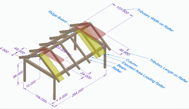
- Students Do. Direct students to observe the pavilion models, and find the names of several structural members written on the models. This step is to familiarize students with the structural members and their appropriate names, as well as help students gain an overall picture of the shape their structures will have.
- Check for understanding.
- Do. Give students some time to observe the models. Check for understanding by asking students to point to a:
- Column (aka post) – a structural member transferring forces from a beam to the ground or foundation.
- Beam (aka eave) – a structural member transferring loads from rafters to columns
- Rafter – a structural member that transfers forces from roof sheathing to a wall and ridge board.
- Ridge board – a board on the peak of the roof designed to allow connection points for rafters. All load is transferred to the wall columns.
- Do. Give students some time to observe the models. Check for understanding by asking students to point to a:
- Example.
- Tell. “We are going to use this model for our example of post and beam architecture. What difference do you notice between this model and yours so far?” Rafters. Ridge beam. “In this lesson, you will determine how you need to design your rafters so that they can appropriately support the load of snow and other materials on the roof. Through this lesson and the next you will also learn how the forces of the load flow through the rafters to the beams, and then into the columns.”
- Calculation overview.
- Tell. “You already know the total load on your roof from our last lesson, (Should be labeled Total Roof Load) now we will figure out the total force on the sheathing, or roofing materials, between each pair of rafters. This will help us figure out how many rafters we should have so that our sheathing won’t break or get holes from having to span too great a distance.”
- Tributary length and width.
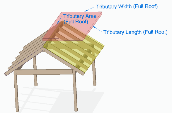
- Tell. “The sheathing material covers a surface that is defined by the rafters, ridge beam, and beam. If we needed to know how much material we need to roof the house, we could calculate the area of this surface by multiplying the length of the rafter by the length of the beam. However, since we are concerned instead about the load or force placed on the roof, we instead need to calculate the horizontal area above the roof. This area is called the tributary area.”
- Define tributary area.
- Tell. “We think of the rafters as absorbing the force from the snow, or other load, resting on them. This area, which they absorb the force from, is the tributary area.”
- Teach. Tributary Area – The horizontal distance between the beam and ridge (tributary width), multiplied by the length of the roof, along the ridge (tributary length).
- Tell. “To measure the tributary width, we would not put a tape measure along the roof surface as that would not be horizontal. Instead, you can think of measuring across from one beam to a point directly under the ridge board, or taking the width of your structure and dividing that by two assuming it’s a roof with a ridge in the middle. Dividing by two gives you the horizontal measurement of just one surface of the roof.”
- Cardboard manipulatives.
- Do. Pass out the pieces of cardboard sized for the tributary area.
- Students Do. Direct students to place them on the roof and estimate their size. Have students compare the cardboard area to the roof both when they hold the cardboard horizontal in the air, and when they hold it directly on the roof surface.
- Ask. “Is it bigger or smaller than this half of the roof surface?” A little smaller than half the roof.
- Position the manipulative.
- Students Do. Direct students to hold the cardboard horizontally even with the peak of the roof. Direct students to use their fingers to measure where the cardboard would line up with the structure.
- Ask. “Where does the cardboard line up?” Students should tell you it lines up with the part of the roof that is above the beam? This is the tributary area on one side of a sloped roof.”
- Effect of triangular roof.
- Tell. “For a sloped or gabled roof the surface of the roof is different from the tributary area. The steepness of the roof makes it so that the tributary area that we use to calculate snow load is slightly smaller than the total surface area of the roof. We also recognize half of the tributary load goes to one rafter while the other half goes to the rafter next to it. Thus half the load goes onto one set of rafters and half onto the other set.”
- Why tributary area?
- Teach. If students have questions about why we use the tributary area instead of surface area, explain how most of the load (both the snow load, and the load of any people on the roof) is applied to the roof vertically. For example, the snow landing on the roof will be the snow that passes through a horizontal plane above the roof. Making the roof steeper will increase the surface area, but will not increase the amount of snow that falls in that area. Granted, a larger surface area will require more roofing materials, which will increase the dead load somewhat, but this is a small enough difference that it is covered by our original estimation of the dead load.
- Review.
- Teach. Explain these two definitions again:
- Tributary Length – a measurement along the ridge board from one end of the home to the other.
- Tributary Width – a horizontal measurement parallel to the ground from the beam to a point directly below the ridge board.
- Teach. Explain these two definitions again:
Sheathing Demonstration (Optional)
This demonstration is meant to show students that spanning sheathing between two rafters for an entire roof will not support a load. The sheathing fails without extra rafter supports. With proper rafter spacing the sheathing will not fail. This demonstration uses the pavilion models, two pieces of balsa sheets measuring 12” by 4” by ⅛”. The balsa will be clamped to the end rafters and tissue paper will be spread across and failed by loading it up with washers.
- Pass out materials.
- Do. Distribute the materials for this portion: the pavilion models, glue dot rolls, weights (washers), balsa sheets, and clamps.
- Sheathing test.
- Tell. “The frame of the roofs you will build are reasonably strong, but the roofing material is not. We are going to see how well it will support the sheathing that we will put on top of our roof.”
- Sheathing test setup.
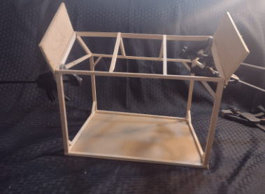
- Do. Clamp the balsa sheets to the two rafters on the edge of the pavilions roof. Essentially these balsa pieces are extending the height of the edge rafters above all the others by a few inches. They should be clamped so they run parallel to the existing rafter.
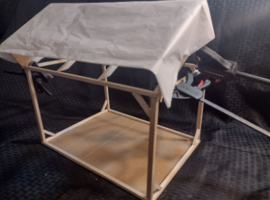
- Tell. “Put glue dots on the outside edge of this rafter extension. They don’t need to be perfect. Then put down the tissue paper stretched flat so it spans between these two rafters, and covers this half of the roof.”
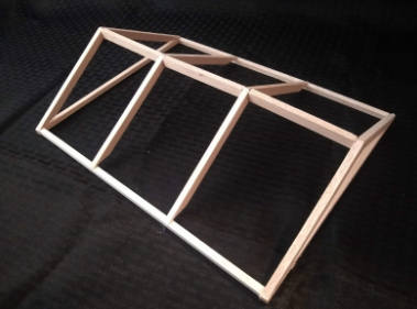
- Note: The setup should look something like the following two pictures. These pictures show a student model instead of the pavilion model, but the setup is the same.
- Sheathing test.
- Tell. “Place washers on the tissue paper (roof sheathing), until it collapses, tears, or pulls off of the glue dots. Note how many washers were supported before the sheathing failed.”
- More sheathing test directions (to compare).
- Tell. “Now, remove the rafter extensions and place glue dots on the rafters that they were clamped to. Spread tissue paper over the roof system with equal spaced rafters and repeat the test with the washers.” Note: if the sheathing does not fail even with the maximum number of washers, that is okay. Just have students note that the roof supported the max number.
- Debrief.
- Do. Ask students how many washers it took to fail the roof with and without the rafters.
- Ask. “Why did the rafters help the sheathing support more weight?”
- Tell. “In standard house construction, ⅝” plywood is used as the roofing material, but it can buckle when significant weight is placed on it. We could build our roofs out of thicker material, but then they would be heavier and more expensive.”
- Conclude the testing.
- Tell. “The models you are building are strong because of the balsa wood’s size relative to your model. At larger sizes this advantage will go away, but we’ve calculated out what might happen at those sizes. What happened to your tissue paper roof happens to real roofs too. If the span between rafters is too large to support the load that the sheathing distributes to the rafters then you get a hole in your roof.”
Calculating Tributary Area
- Calculations work time.
- Do. Aid students in calculating the tributary area for their particular structure. Note: For students planning on a symmetrical gable roof (probably most students) this will be their structure length times half the width. This number ought to be half the Structure Area calculated in Columns of Calculation . Label this calculation ‘Tributary Area’.
- Total Rafter Force.
- Students Do. Calculate total force on one set of rafters by multiplying Tributary Area and Total Roof Load (from Columns of Calculation). Label this ‘Total Rafter Force’.
- Max sheathing strength.
- Tell. “Based on known data, you have been told that any span of sheathing between two rafters can support up to 800 pounds.”
- Decide on rafter spacing.
- Tell. “There are many correct ways to space rafters, but your rafters must be close enough so that no gap has over 800 pounds loaded on it. Given this, determine the minimum number of rafters required for your roof. What calculation do you need to do to find this value? How far apart will these rafters be spaced?”
- Teach. If students are struggling, give the example below.
- For example, suppose our total roof load was 30 psf. If our tributary area for one side of the roof is 100 sq ft, then you multiply this by 30 psf to get 3000 lbs. If we can support 800 lbs per span, then we need 3000/800=3.75 evenly spaced spans. However, since ‘0.75 of a span’ isn’t a thing, we round this up to 4. Note that we must always round up (never down), since the value we are calculating is the minimum. If we are to have 4 spans, we need to have 5 rafters, including both rafters on the ends. Now that we know how many spans and rafters we need, we can calculate the spacing between rafters. Since we have 4 spans, we need to divide the tributary length by 4 to calculate the width of each span.
- Note: This is a very simple way of calculating this, there are better ways but this one will serve to get the students thinking on spacing.
Assemble the Roof
- Introduce building.
- Tell. “A roof completes your structure. The earliest roofs were made of light, readily available, and partially waterproof materials. They weren’t very durable but were easy to fix. The early Chinese made clay tiles. Thatched roofs were common in the medieval period. Wooden shingles replaced them and have been replaced by modern composite shingles. The structure of roofs has changed little in that time.”
- Structure of the roof.
- Tell. “For post and beam architecture the roof of choice is typically a gabled roof. This kind of roof offers two advantages. First, it divides the force of the load into two halves on each side of it. Also, it lets snow fall off when the temperature increases. The alternative is going up on top of your flat roof in the winter to shovel the snow off of it, something people with flat roofs in cold climates sometimes have to do in the winter.”
- Overall plan.
- Tell. “We are going to build a roof to go atop your columns. We’ll start by building a second box.”
- Height limitation.
- Tell. “Your roof plus the rest of your structure cannot exceed either 10 or 13 feet depending on your earlier design choice. When planning the height of your roof keep this in mind. Don’t forget to include the thickness of the materials.”
- Second footprint box.
- Tell. “I’m sure you know at this point how to build a second footprint box to go on top of your columns.”
- Define height limitation.
- Tell. “How can you calculate or measure the maximum height of the roof portion of your structure? Measure or calculate the structure’s current height, then subtract that from 10 or 13.”
Assemble Gables
- Gable assembly.
- Tell. “Creating the gable pieces and assembling them can be tricky. There are some very specific angles that need to be cut on the pieces. If they are off by a little the gables members won’t meet flat and lay flat, which impacts strength.”
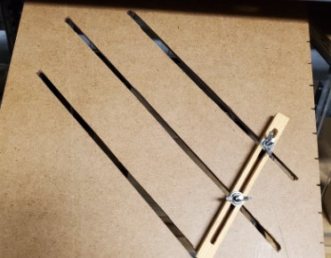
- Angle/Length jig.
- Tell. “We made an adjustable guide to help. To use it you need to know two numbers, the height you have left to work with for your total structure, and the horizontal distance that each rafter covers. This is the same as the tributary width, or half of the width of your structure, if you have a symmetrical gable.”
- Gable cuts.
- Teach. Demonstrate this procedure on the jig itself. (Jig is shown in the photo below)
- Start with your cutting jig clamped to the table. Place a piece of balsa on the jig and line it up according to the height of your roof and the horizontal distance of your rafters. For example, if your roof is 2 inches tall, and your rafters span 5 inches, (i.e. your building is 10 inches wide), you would place the balsa so that it hangs off of the jig directly over the second notch on one side, and directly over the fifth notch on the adjacent side of the jig. Slide the adjustable fence next to the balsa, and tighten it into place. Put down a piece of sticky backed paper as a drip pad for later.
- Then lay your wood down, hold it firmly in place next to the fence, (you may find it helpful to clamp the balsa to the fence) and cut off the portion that is hanging over each edge of the jig, using the side of the jig to guide the saw. You will make a cut on each end of the piece of wood (without moving it between cuts) so that both ends are angled correctly.
- Repeat this process to make as many rafters as you need. Remember to make rafters for both sides of the gable.
- Take two rafters, and glue their ends together with glue dots, so that they form a gable peak. Note: Make sure that the ends with the correct angle for the peak are used, so that it makes the correct truss shape. Repeat this for each pair of rafters.
- Hold the gables in position on top of your new footprint box (roof box), and check that they line up with the edges and sit flat. Make any small adjustments if needed.
- Note: If pieces are slightly off, the exacto knife can be used to whittle away any wood that is too large or a strategically placed glue dot can span a gap. The instructor may be able to help make this more precise.
- Teach. Demonstrate this procedure on the jig itself. (Jig is shown in the photo below)
- Beam scoring.
- Students Do. Direct students to mark their chosen rafter spacing on their roof box. These spacings should be measured from the same point on each rafter. i.e. students should measure from the left side of one rafter to the left side of the next, or from the right side of one rafter to the right side of the next. It is important that students are consistent about which side they use to measure.
- Check student work.
- Do. Check that students have made their marks evenly on both sides of their model and have the corresponding wood thickness to go with them. Be sure students know where to line up their rafters relative to the marks.
- Attach the gables.
- Students Do. Glue each gable in place on top of the roof box. You can use either hot glue or glue dots for this step.
- Secure with hot glue.
- Students Do. Once the roof is assembled, use hot glue to reinforce any joints made with glue dots.
- Note: Using glue dots at first, especially on the ridge joint, allows enough flexibility to account for the angles not being cut perfectly, but once all sides are attached in place, the hot glue adds much more rigidity.
- Ridge beam.
- Students Do. If the roof trusses are not parallel to one another a student can (a) add small segments of wood between each rafter pair at the ridge to hold them in place, or (b) add a full length ridge beam directly underneath the point of the gables. Option b will work best if the rafters meet at something close to a 90° angle, but will still be helpful even if it only attaches to one side of the rafters.
- At this point, students assemblies should look roughly like the picture below.
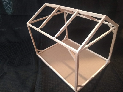
- Completing the model.
- Students Do. Students should now have an assembled roof with rafters. To complete their model, they should place this assembly on top of the columns and foundation box that were assembled in MB3, and glue it down. At this point, they may choose to add more braces or hot glue to stabilize their model. Their model should now look like the picture below.
- If time permits.
- Students Do. If students have time after they have added rafters, they may add sheathing to one half of their roof.
- Endpoint.
- Do. At the end of this session, students should have a complete model of their structure. Look at each student’s model to ensure it is properly constructed and aligns with the height limitation.
Standards Alignment
NGSS Standards Alignment:
- SEP 5 - Using mathematics and computational thinking
- CCC 6 - Structure and function
- HS-ETS1-2
CCSS Standards Alignment:
- CC.9-10.R.ST.3, CC.9-10.R.ST.4, CC.9-10.R.ST.5, CC.9-10.R.ST.7, CC.11-12.R.ST.3, CC.11-12.R.ST.4, CC.11-12.R.ST.5, CC.11-12.R.ST.7
- CC.9-12.G.GMD.4, CC.9-12.G.MG.1, CC.9-12.G.MG.2, CC.9-12.G.MG.3, CC.9-12.G.SRT.6, CC.9-12.G.SRT.7, CC.9-12.G.SRT.8